
Click here!

F4 2-3S 20A AIO FC V1 is specifically designed for HD VTX, utilizing 2-3S batteries for enhancing the flight experience. It features a dual BEC solution that delivers stable power outputs of 9V@2A for DJI O3 and 5V@3A for external devices. With a 20A ESC, it enables agile flight and increases dynamic. And connector for DJI O3 HD VTX and USB port for easy installation and maintenance. Ideal for HD VTX whoop enthusiasts, offering a heightened level of professionalism and convenience with this FC option.
Check out all our Whoop Style AIO Flight Controllers and the rest of our BetaFPV Products!

*The output current of BEC will decrease as the temperature increases
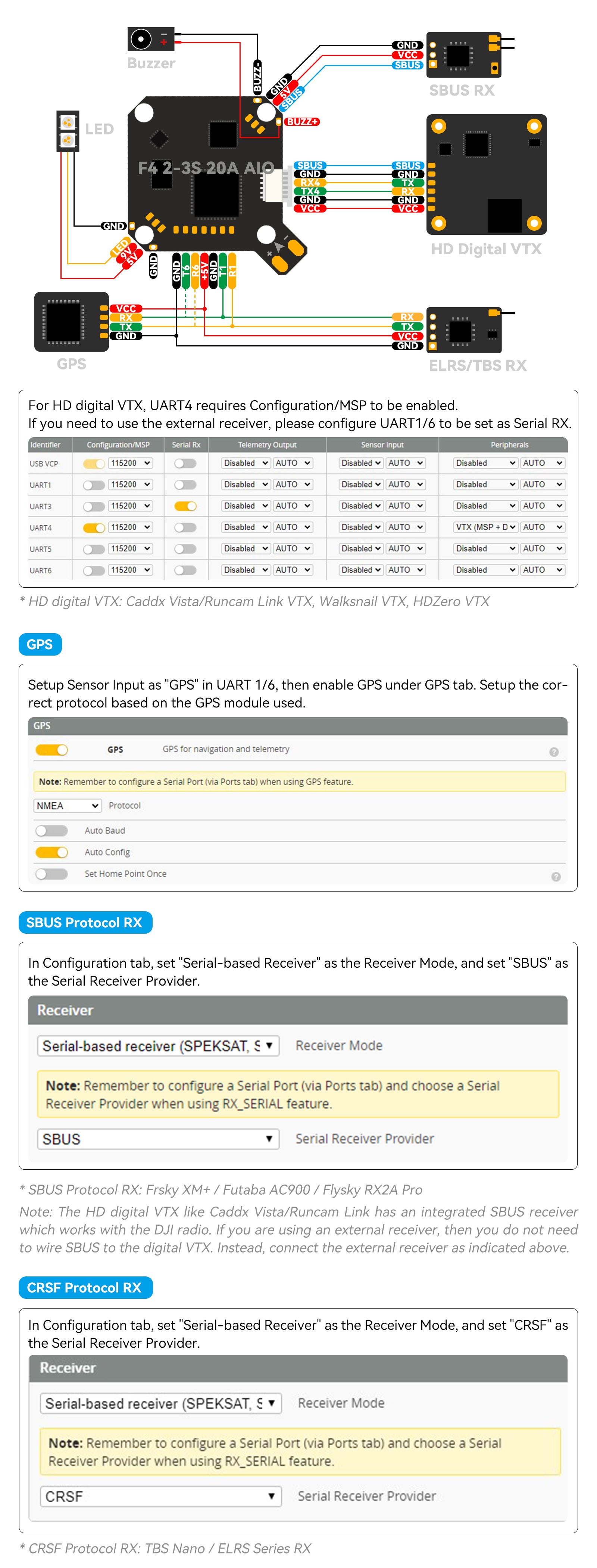
Below is the diagram for F4 2-3S 20A AIO FC V1
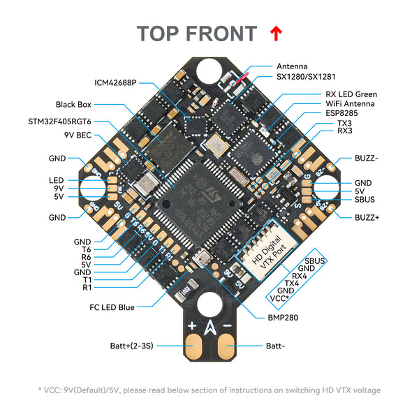
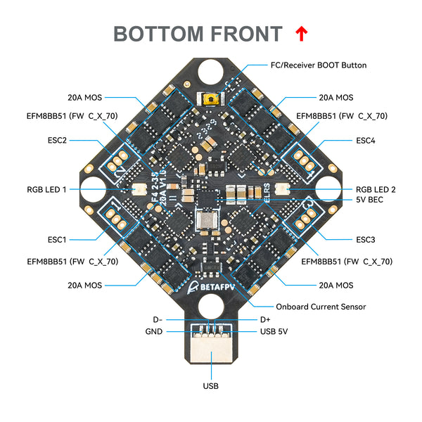
We upgraded the FC from F4 1S 12A AIO FC V3 to F4 2-3S 20A AIO FC V1. The upgraded FC features an ESC with a pulse overcurrent capacity of 25A, ensuring stable operation of the flight controller even in the event of motor stalling. The addition of a 9V 2A BEC power supply ensures the stable operation of the DJI O3 HD VTX when the battery voltage is low. It also includes a DJI O3 6-pin PMU allowing for connection to HD VTX without soldering. It integrates features such as a 16MB black box, with support for GPS, external receivers, and other devices. The redesigned solder pad layout and USB connector make installation and maintenance easier and more convenient.
| F4 1S 12A AIO FC V3 | F4 2-3S 20A AIO FC V1 | |
| Weight | 4.23g | 5.58g |
| BEC |
5V@3A for External RX |
5V@3A for External RX 9V@2A for DJI O3 |
| Connector for DJI O3 | Not support | Support |
| ESC Current | 12A | 20A |
| ESC Input Voltage |
1-2S | 2-3S |
| Number of Serial Ports | 2*UART, 1*SBUS | 4*UART, 1*SBUS |
Note: If you use the F4 2-3S 20A AIO FC V1, the serial port of the SBUS receiver is UART5 while F4 1S 12A AIO Brushless FC V3 is UART6.
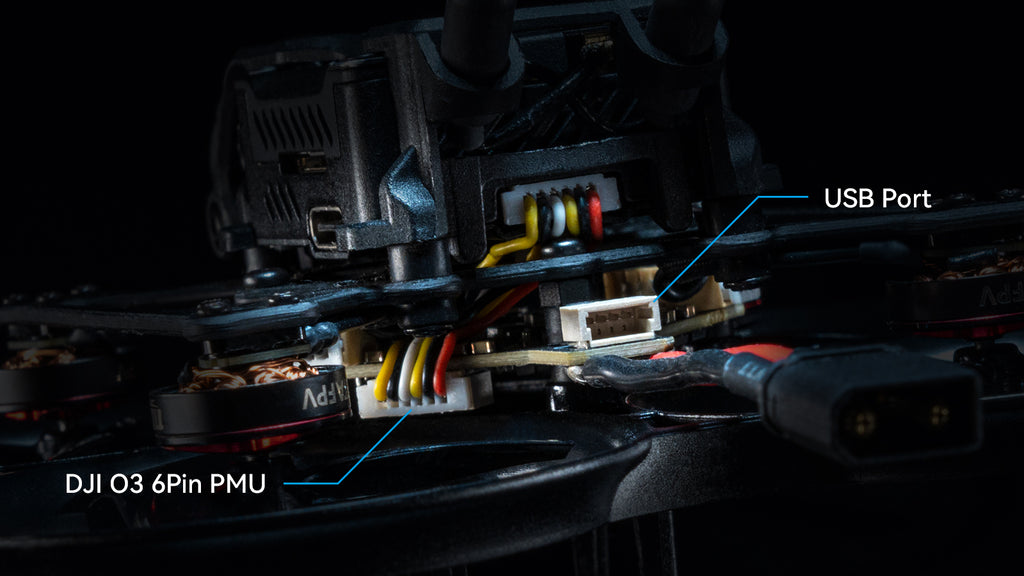
F4 2-3S 20A AIO FC V1 also has extended the USB port to the end for easier parameter adjustment and wiring. And a new DJI O3 6-pin PMU has been added for convenient installation and maintenance.
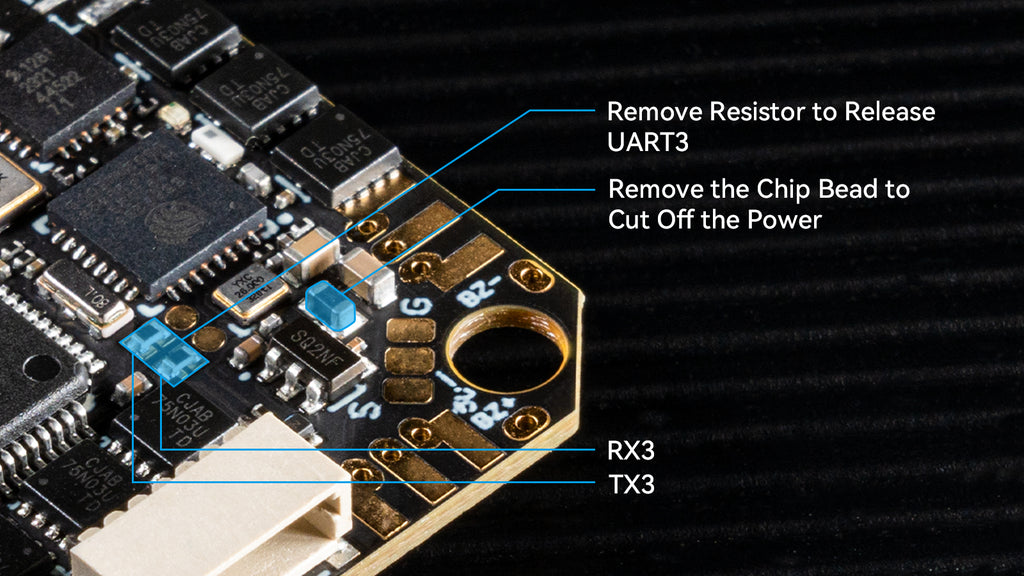
Power cutoff: Removing the chip bead disconnects the power supply, and to reuse the onboard ELRS receiver, soldering the solder pads together restores power.
UART3 release: Removing two resistors on the solder pads releases UART3. The left side is TX3, and the right side is RX3. To reconnect, solder the solder pads together when reusing the onboard ELRS receiver.
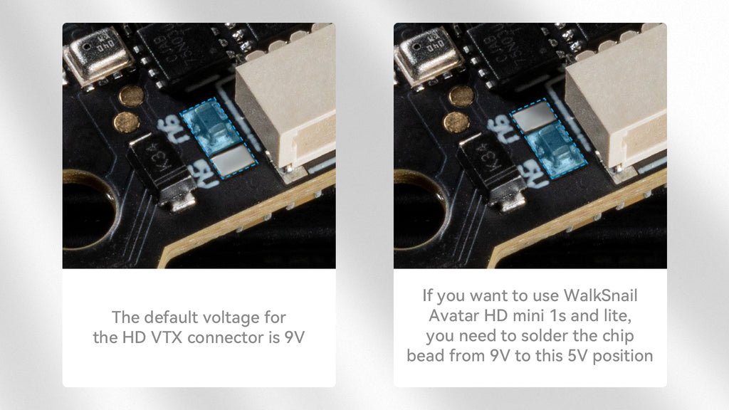
Voltage Switch: The HD VTX connector defaults to 9V. The chip bead is soldered between the 9V pad and the middle pad. To use WalkSnail Avatar HD mini 1s and Lite, please ensure the power supply voltage is 5V. Remove the chip bead first from the 9V pad and solder it between the middle pad and the 5V pad. Alternatively, you can use solder instead the chip bead to switch between the 5V and 9V pads.
Motor choice: Avoid selecting motors with excessively high KV ratings, as motors above 20,000KV are prone to burn.
FC firmware: Betaflight_4.4.1_BETAFVF405
Download the firmware and CLI dump file
Reference link:
With BB51 ESC solution, F4 2-3S 20A AIO FC V1 is based on BLHeliSuite16714903 with Bluejay ESC firmware, it supports bidirectional D-shot and RPM filtering in Betaflight, offers 24KHz, 48KHz, and 96KHz fixed PWM frequency for options, and custom start-up melodies. F4 2-3S 20A AIO FC V1 default factory setting is 48KHz and it doesn’t recommend upgrading the 96KHz, or it might cause an error in the motor idle setting, not spinning when disarmed.
DO NOT flash the firmware with a shorter interval, otherwise, there will be a certain chance of stalling and burning the flight controller.

Serial ELRS 2.4G RX uses the Crossfire serial protocol (CRSF protocol) to communicate between the receiver and the flight controller board. So the Serial ELRS 2.4G RX is available to support upgrading to ELRS V3 with no need to flash Betaflight flight controller firmware.
The Serial ELRS 2.4G RX can be updated via Wi-Fi or Betaflight serial passthrough. Here is the way to update the Serial ELRS 2.4G RX firmware through passthrough.
How to flash firmware via Wi-Fi here.
Please note that the board reserves two serial ports and a standard SBUS port, which is available for the external CRSF protocol receiver or GPS module, and SBUS protocol receiver. You can refer to the below picture.
{"one"=>"Select 2 or 3 items to compare", "other"=>"{{ count }} of 3 items selected"}